 LNEYA
LNEYA
 简体中文
简体中文
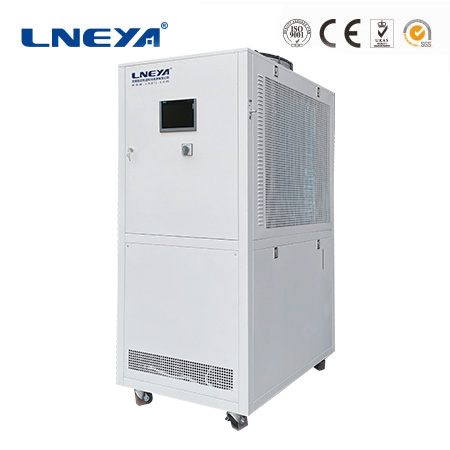
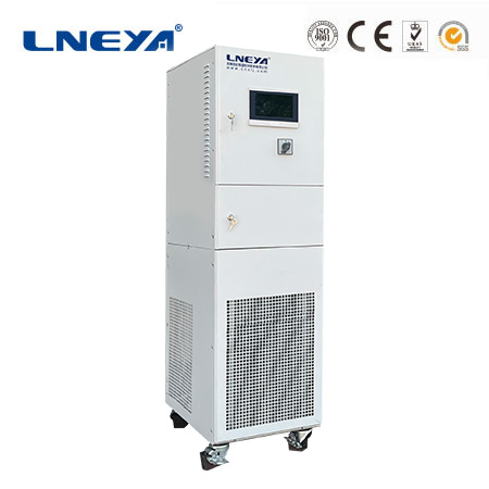
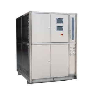
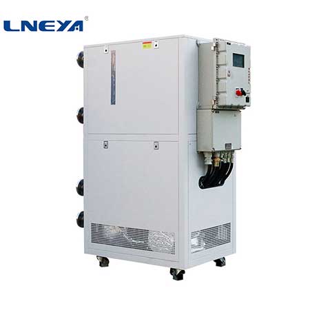
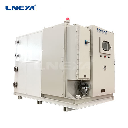
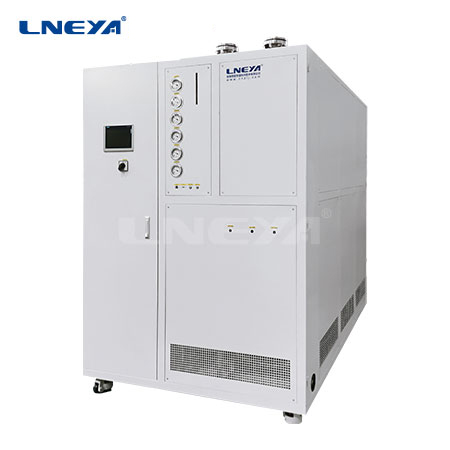

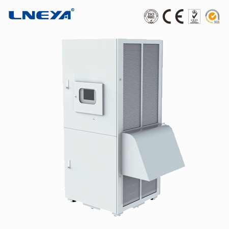
Battery Pack Cooling
Contact us today for the perfect temperature control solution
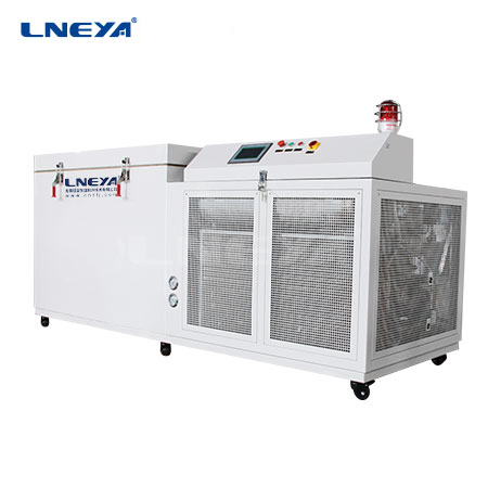
As the power source of the new energy vehicle power battery, the heat generated by charging and discharging will always exist. The performance of power batteries is closely related to battery temperature.
In order to extend the service life of the power battery as much as possible and obtain maximum power, the battery needs to be used within the specified temperature range. In principle, the power battery unit is in an operable state within the range of -40°C to +55°C (actual battery temperature). Therefore, current new energy power battery units are equipped with cooling devices.
Power battery cooling systems include air-conditioning circulation cooling, water-cooling and air-cooling.
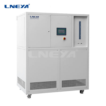
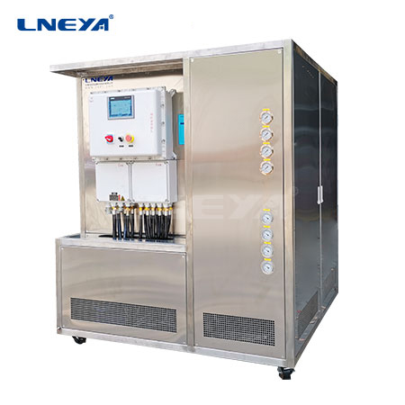
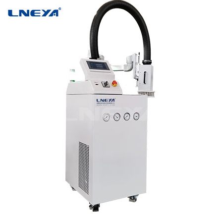
1. Air conditioning circulation cooling type
The power battery unit is directly cooled by coolant, and the coolant circulation loop and the refrigerant circulation loop are connected through a coolant-refrigerant heat exchanger (ie, cooling unit). Therefore, the refrigerant circulation circuit of the air conditioning system consists of two parallel branches. One is used to cool the interior space of the vehicle, and the other is used to cool the power battery unit. Each of the two branches has an expansion and shut-off combination valve, and two independent cooling systems.
Cooling working principle:
An electric coolant pump delivers coolant through the coolant circuit. As long as the temperature of the coolant is lower than that of the battery module, the battery module can be cooled using only the circulating flow of the coolant. The coolant temperature rises and is insufficient to keep the battery module temperature within the expected range.
Therefore, the temperature of the coolant must be reduced, using a coolant-refrigerant heat exchanger (i.e., cooling unit). This is the interface between the power battery coolant circulation loop and the air conditioning system refrigerant circulation loop.
If the combined expansion and shutoff valve on the cooling unit is electrically activated and opened, liquid refrigerant will flow into the cooling unit and evaporate. This absorbs heat from the ambient air and is therefore a coolant flowing through the coolant circuit. The electric air conditioning compressor (EKK) compresses the refrigerant again and delivers it to the capacitor, where it becomes liquid again. The refrigerant can therefore absorb heat again.
In order to ensure that the coolant channels dissipate heat from the battery module, the entire surface of the cooling channels must be pressed against the battery module with an evenly distributed force. This pressing force is generated by spring bars embedded in the coolant channels. The spring bars are adapted to the battery module geometry and the lower housing half.
The spring bars of the heat exchanger are supported on the lower part of the housing of the high-voltage battery unit, thereby pressing the coolant channels against the battery module.
The electric coolant pump in the coolant circulation circuit of the power battery unit has a rated power of 50W. The electric coolant pump is fixed with a bracket on the cooling unit, which is installed in the rear right corner of the power battery.
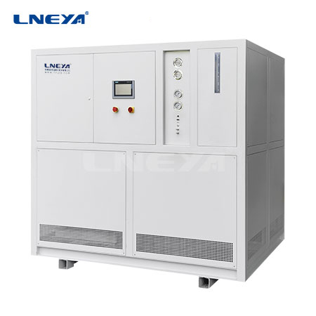
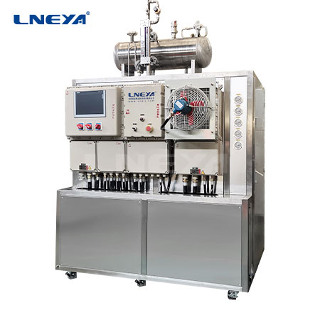
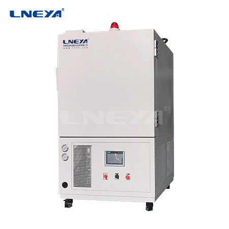
2.Water-cooled
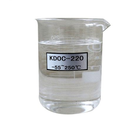
The water-cooled power battery cooling system uses special coolant to flow in the coolant pipeline inside the power battery to transfer the heat generated by the power battery to the coolant, thereby reducing the temperature of the power battery.
The cooling system uses the principle of heat conduction to keep the drive motor, inverter (PEB) and power battery pack at the optimal operating temperature by circulating coolant in each independent cooling system loop. The coolant is a mixture of 50% water and 50% Organic Acid Technology (OAT). Coolant needs to be changed regularly to maintain its optimal efficiency and corrosion resistance.
01.Expansion water tank
The expansion water tank is equipped with a pressure relief valve and is installed on the inverter (PEB) tray. The overflow pipe is connected to the liquid outlet pipe of the battery cooler, and the liquid outlet pipe is connected to the cooling water pipe tee. There are “MAX” and “MIN” scale marks on the outside of the expansion tank for easy observation of the coolant level.
02.Hose
Rubber coolant hoses carry coolant between components, and spring clamps secure the hoses to each component. The power battery cooling system (ESS) hoses are arranged in the front cabin and under the rear floor assembly.
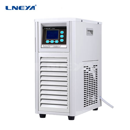
03. Cooling water pump
The coolant pump of the power battery cooling system passes through the mounting bracket and is fixed on the body chassis by two bolts. Its operation circulates the high-voltage battery pack cooling system.
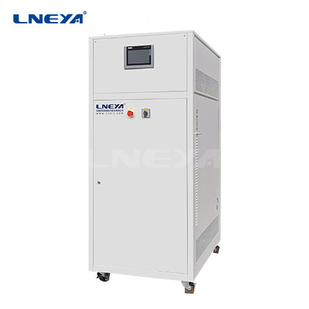
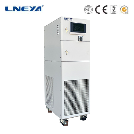
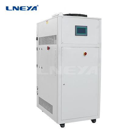
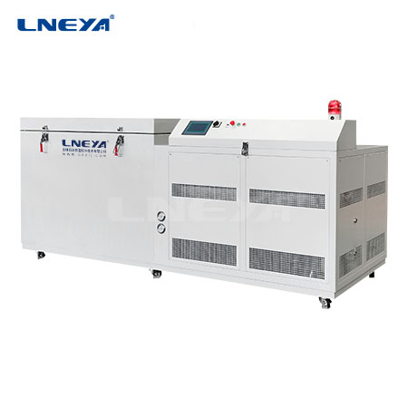
04.Battery chiller
The battery chiller is a key component of the power battery cooling system. It is responsible for maintaining the power battery at an appropriate operating temperature so that the discharge performance of the power battery is at its best. The battery chiller is mainly composed of a heat exchanger, an expansion valve with a solenoid valve, a pipeline interface and a bracket. The heat exchanger is mainly used for heat exchange between the power battery coolant and the refrigerant of the refrigeration system, and transfers the heat in the power battery coolant to the refrigerant.
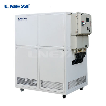
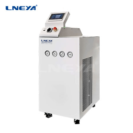
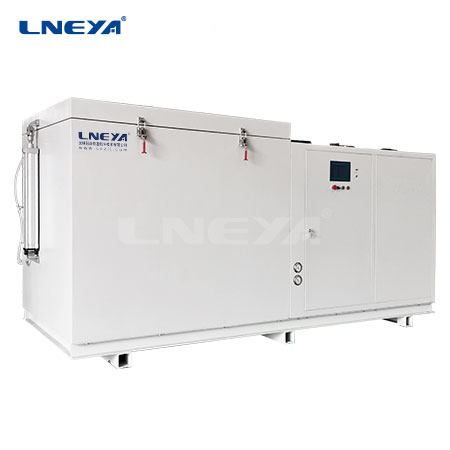
3. Air-cooled type
The air-cooled power battery cooling system uses a cooling fan to draw air from inside the cabin into the power battery box to cool the power battery and the power battery control unit and other components.
The air inside the cabin flows in through the air intake duct located on the rear window sill decorative panel, and flows downward through the power battery or DC-DC converter (hybrid vehicle converter) to reduce the temperature of the power battery and DC-DC converter (hybrid vehicle converter). device) temperature. Air is exhausted from the vehicle through the exhaust pipe.
The air inside the cabin flows in through the air intake pipe located on the rear window sill decorative panel, flows downward through the power battery to reduce the temperature of the power battery, and then passes through electrical components such as the BMS and total positive and negative relays. After lowering its own temperature, it is passed through the exhaust pipe. Air is removed from the car.
The cooling fan is a DC low-voltage fan equipped with an independent DC-DC converter; when the cooling fan is working, the current flows from the power battery through the DC-DC converter to convert the 350V DC high voltage into a DC low voltage of 12V ~ 16V, providing Give cooling fan.
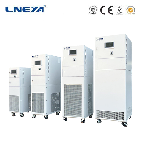
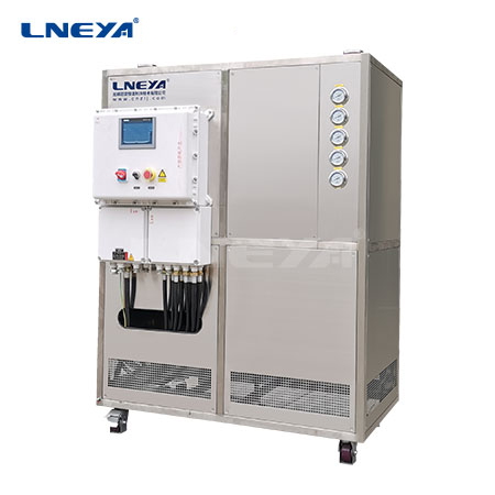
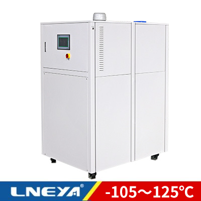
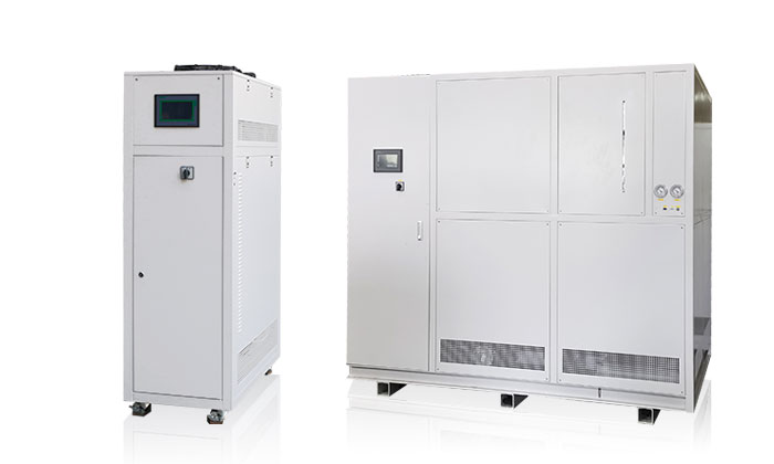
We provide complete temperature control systems design and manufacturing. From standard models to complete customized products up to 900 tons. We specialize in customer service and are dedicated to helping each customer have the optimal temperature control system for their specific need.
We provide non-standard customized solutions. Both single cooling chillers and cooling & heating combo units are available.
Email: info@lneya.com WeChat ID: +8615251628237 WhatsApp: +86 17851209193
Copyright information belongs to lneya-online.com, please contact email for details: lilia@lneya.com
Or scan the WhatsApp or WeChat QR code below to contact us.
WhatsAPP WeChat